Choosing a Cluster Configuration
ISC High Performance hosts the annual Student Cluster Competition (SCC) for which students build a cluster and compete in different application categories for the highest performance under a power budget. At SCC 2019 in Frankfurt, Germany, the power limit is set at 3kW. This blog posts covers the proposal for our cluster architecture.
Performance vs Power Draw
For the SCC, the team considered two prize categories: The overall prize and the award for the highest Linpack performance. While the former is awarded based on the weighted performance on all presented benchmarks and applications, the latter’s evaluation is solely based on a single benchmark performance. Choosing a cluster architecture optimised for the set of called applications is a prerequisite for high performance results at the competition.
The cluster comprises CPU, memory, storage, motherboard, accelerators (GPU), network cards and cooling system (fans vs. liquid cooling). From these groups the team identified CPU and GPU as most important factors impacting performance and power consumption. Peripherals like memory, motherboard, storage and cooling set a baseline for power consumption as we assume a rather negligible, constant power draw from these. The author assumes the following power draw:
- RAM: 5 Watt
- Motherboard: 50 Watt
- Storage (SSD): 5 Watt
- Liquid Cooling: 150 Watt
Liquid cooling has the potential to leverage power efficiency. Last years’ teams gained increased performance per Watt with a liquid cooling system drawing around 150 Watt at maximum. Besides the performance gain, liquid cooling systems bear the risk of spillage of liquid, damaging components and risking the cluster’s operability on the whole. Deploying liquid cooling with the latest processors requires specialised accessories and potential adaptations of the chassis. Eventually, the team together with the sponsor decided to include a fan-cooled chassis instead of liquid cooling. The team’s sponsor Boston Ltd. provided eight CPU nodes and one GPU node. In fact, the GPU node was a NVIDIA DGX-1 server carrying eight NVIDIA Tesla V100 GPU with 32 GB of memory each, connected via 8-way NVLink on a single node.
Power draw
Choosing the right number and architecture composition of CPU and GPU
and assuming TDP as power draw at peak performance, the author compares
the processors’ thermal design power (TDP). Figure
3.1 visualises the tradeoffs between Intel
Xeon Platinum 8180 (CPU) and NVIDIA Tesla V100 (GPU) for quantity
selection. Idle and maximum power consumption of the processors offered
to the team are presented in Table
3.2.
Estimated idle and maximum power consumption:
| Processor | Idle | Max |
|---|---|---|
| Intel Xeon Platinum 8180 | 10W | 205W |
| Intel Xeon Gold 6126 | 10W | 125W |
| Intel Xeon Gold 6140 | 10W | 140W |
| NVIDIA Tesla V100 | 36W | 300W |
The higher the cluster performance within the power budget, the better.
Scenario (12 CPU, 8 GPU) stays within the power limit of 3000 Watt
while still maintaining budget back-up for other components such as RAM,
motherboard and fan cooling. Scenario (12 CPU, 4 GPU) maintains too
low performance and additional CPU and GPU could be added to the
configuration. Scenarios (14 CPU, 8 GPU), (12 CPU, 10 GPU) and
(14 CPU, 9 GPU) exceed the power budget of 3000 Watt. Figure
3.1 does not take other components’ power
consumption into account but visualises hardware configurations based on
idle an peak power draw. In alternative to idle and peak performance, an
over-specified system running at lower utilisation than 100% might
benefit optimised performance.
Figure 3.1 shows the processor combinations and their power consumption. The
x-axis names combinations of Intel Xeon Platinum 8180 (CPU)
and NVIDIA Tesla V100 (GPU) quantities. The non-dashed bars
(GPU_max CPU_idle) represent GPU running at maximum
performance with maximum power consumption and CPU running idle. The
dashed bars (CPU_max GPU_idle) represent CPU running at
maximum performance and maximum power consumption with GPU running
idle.
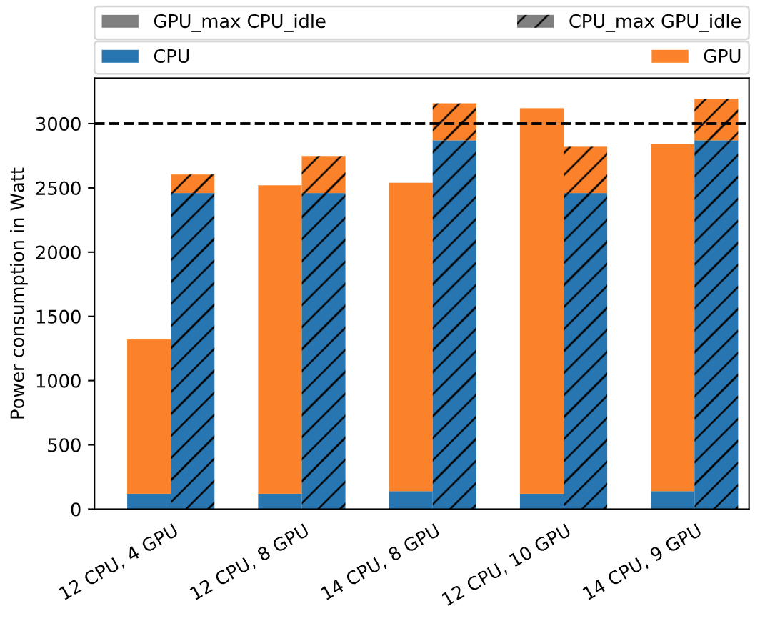
Table 3.3 lists the cluster’s final mix of processors used at the competition. From above’s considerations, the hardware sponsor recommended using the listed set of available CPU. Table 3.4 shows the remaining component specifications besides CPU. The final cluster contains nine nodes, 18 CPU and eight GPU.
| Nodes | Processor | Cores | Microarch. | Instruction set | Freq. | TDP |
|---|---|---|---|---|---|---|
| 3 | Xeon Gold 6126 | 12 | Skylake | AVX-512, AVX2, AVX, SSE4.2 | 2.6 | 125 |
| 4 | Xeon Gold 6248 | 20 | Cascade-lake | AVX-512, AVX2, AVX, SSE4.2 | 2.5 | 150 |
| 1 | Xeon Platinum 8176 | 28 | Skylake | AVX-512, AVX2, AVX, SSE4.2 | 2.1 | 165 |
| 1 | Xeon E5-2698V4 | 20 | Broadwell | AVX2 | 2.2 | 135 |
The CPU contained in the cluster are Intel Xeon processors but the mix
of varying processor types comes with the cost of varying core counts,
frequencies, performances and power consumption. The supported
instruction sets are identical for the Skylake and Cascade-lake
generations but Broadwell only supports AVX2 while the former support
up to AVX-512. Compiling libraries and software packages like SWIFT and
OpenFOAM, other team member must choose the lower performing AVX2 if
optimised vectorisation is required and the code is to be run across all
nodes. Alternatively, the GPU node has to be left untouched while
running these applications in order to compile for the higher performing
AVX-512 instruction set. Leaving out the Broadwell node (the GPU node)
for program deployment might waste power draw that could be spent on run
performance. Controlling the different CPU frequencies with the Linux
tool cpupower is possible but working on heterogeneous processors
across the cluster led to unbalanced performance as does the varying
processor specifications in general.
Cluster components and their specification:
| Component | Specification |
|---|---|
| Memory | 128 GB per node, 256 GB in the DGX-1 Server |
| Storage | 1 TB in the headnode, 1 TB in the DGX-1 Server |
| Networking | Mellanox 36x 100 Gbps Infiniband Switch |
| Accelerator | 8x NVIDIA Tesla V100 (32 GB VRAM) in an NVIDIA DGX-1 Server, 8-way NVLink |
| Cooling | Fan-cooled system chassis |
Software considerations
For the OS we will use CentOS Linux 7. The cluster’s software stack is set up to support the announced benchmarks and applications. Nevertheless, installing the required compilers, tools and libraries the team maintains a broad support for common HPC applications. This software stack and the team’s experience with it gained during preparation lets us easily adapt to changing requirements i.e. the secret application.
The team tested different compilers and overall the Intel compilers demonstrated better performance than any other compiler. In general, we prefer open-source due to the community support and the wide ranging documentation and discussions that are publicly accessible but because of the performance Intel compilers are our primary choice. Nevertheless, we also consider other compilers depending on the availability and performance - including GNU and PGI Compilers.
Our software stack includes different MPI implementations including but not limited to OpenMPI and MPICH. We are currently also experimenting with MVAPICH2. Regarding MPI implementations we acknowledge several restrictions: As recommended by HPCAC we will avoid Open MPI versions between 1.10.3 to 1.10.6 due to the known timer bug. Horovod users experienced problems with Open MPI 3.1.3. It is recommended to either downgrade to Open MPI 3.1.2 or to upgrade to Open MPI 4.0.0. The team will avoid these versions. For CP2K, the team currently experiments with OpenMPI v3 and v4.
Controlling and tracking power consumption the team uses IPMI2, cpupower and cpupower-frequency-set tools, respectively NVIDIA System Management Interface for GPU. Additional libraries and software packages include:
RapidCFD, cufflink for OpenFOAM
ScaLAPACK, FFTW3, libxsmm and MKL for CP2K
HDF5, ParMETIS, libNUMA and GSL for SWIFT
Anaconda, Nvidia GPU drivers, CUDA Toolkit, cuDNN and NCCL2 for the AI Application (TensorFlow/Horovod)
Controlling GPU performance
The performance of TensorFlow and Horovod for deep learning strongly relies on the cluster’s GPU making it imperative to investigate means by which GPU performance could be maximised while balancing power consumption. Nevertheless, the Student Cluster Competition introduces applications that are not GPU-enabled, making it also necessary to examine how to decrease the GPU’s power consumption when running idle. Previous EPCC student teams were able to turn off Error-correcting code memory (ECC) in order to lower GPU idle power [@ManosFarsarakis]. Decreasing idle GPU power consumption implies increased available power for CPU-focused applications.
NVIDIA System Management Interface (nvidia-smi) provides monitoring
information for NVIDIA’s Tesla devices. The program presents the data in
plain text or XML format. Table
3.2 lists the idle state power draw of
NVIDIA Tesla V100 GPU, contained in a DGX-Station node carrying four
NVIDIA Tesla V100 GPU. These test were conducted while a test system was
available to the team - an NVIDIA DGX-Station. The devices are idle at
34 degrees Celcius and 36 Watt. Their maximum hardware cap is 300 Watt.
Nvidia-smi also provides several management operations for changing
device state and operation modes that adopt performance and power
balance:
Maximum Performance Mode operates the device at its peak Thermal Design Power (TDP) level, thus 300 Watt, see section 3.2 for the NVIDIA Tesla V100 for accelerating applications relying on fastest computational speed and highest available data throughput [@NvidiaVoltaArchWhitepaper].
In Maximum Efficiency Mode the device is run at optimal power efficiency available through the
nvidia-smiinterface (see Max-Q) [@NvidiaVoltaArchWhitepaper].In Persistence Mode the enabled NVIDIA driver remains loaded at all cost, even when no active client exists. This mode minimises driver load latency associated with executing dependent applications like CUDA programs.
GPU Operation Mode (GOM) is capable of disabling device features in favour of reduced power consumption and optimised GPU throughput. GOM offers three operation levels:
All on mode enables all features and runs the device at full speed.
Compute mode is optimised for running compute tasks only. No graphics operations are allowed.
Low Double Precision mode enables and optimises graphics applications that don’t require high bandwidth double precision.
Max-Q defines a configuration that delivers the best performance/watt balance for a given workload. Running in Persistence Mode a user can set power consumption caps for individual devices or a group of devices.
First the persistence mode has to be enbled by issuing:
nvidia-smi -pm 1. To turn off persistence mode:nvidia-smi -pm 0If persistence mode is enabled, set a maximum power consumption of 180 Watt to all detected devices with
nvidia-smi -pl 180To target specific devices use flag
-i device_id, e.g.nvidia-smi -i 0 -pl 180to set the first of many devices in a node to a power cap of 180 Watt.
GPU checks and power draw monitoring
The weekend before the competition, the cluster was shipped from Boston Limited’s headquarters in St Albans near London to the conference venue in Frankfurt. The nodes arrived pre-assembled at the location and only needed to be hung in the chassis, wired and powered on. CPU-only test runs by other team members on Sunday, the setup day before the competition, provided more insights into the overall cluster’s power draw. The setup with nine nodes operated at 1.6 kW at idle. Other team’s idle power draw displayed as live graphs in a Grafana dashboard ranged from 0.5 to 1.2 kW. Competitors’ architectures included pure CPU clusters and setups with older generations GPU - most team’s included accelerators for GPU-enabled applications and benchmarks.
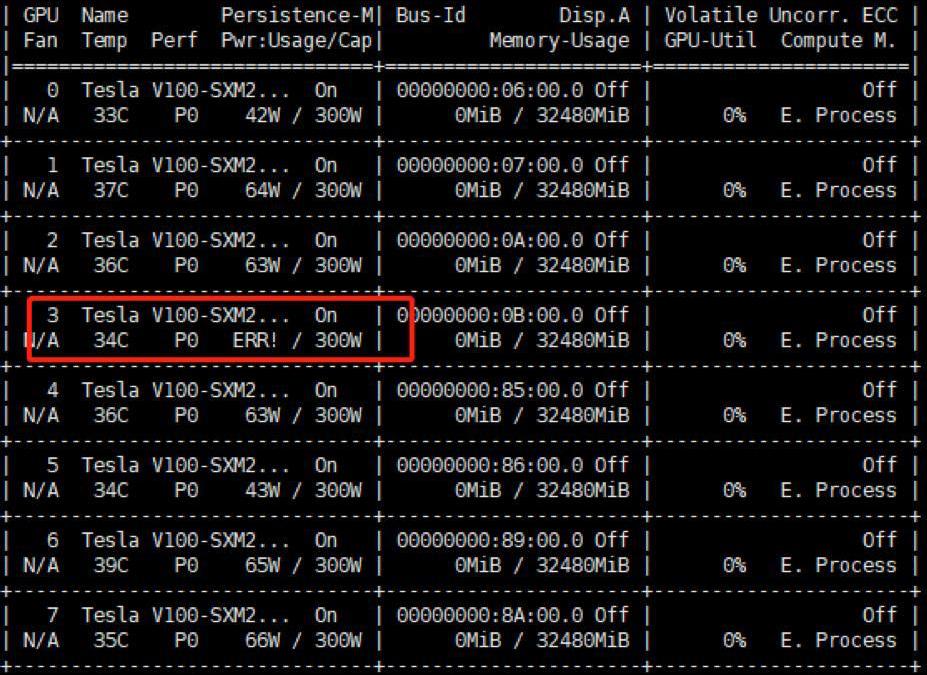
Checking the GPU devices together with other team members who used the
GPU as well, HPL was run first and led to very low results below 10
TFlop/s. Re-runs raised memory errors. Checking the nvidia-smi
interface confirmed the error:
Error on MPI rank 3: memcpy, illegal access. As depicted in Figure
3.2, GPU #3 was not running properly. The GPU
system was shutdown, detached and the determined processor investigated.
A screw had loosened avoiding full device connection. Carefully screwing
tightly resolved the issue. The system was brought back and ready for
operation.
While other team members tested their applications, the author checked on the GPU node’s performance and power draw. Last years’ evaluation metrics for the AI application included peak throughput images per second, the number of input samples that could be processed. 2019’s rules on the AI application focused on evaluating the Intersection-over-union score (IoU) of a prediction with a neural network for semantic image segmentation. The evaluation focus was on the inference at the competition. The resource- and power-intense network training could be dealt with during preparation, prior to the competition. The submission at the competition comprised the application’s inference output on unseen data that the team was provided with at the day of competition.
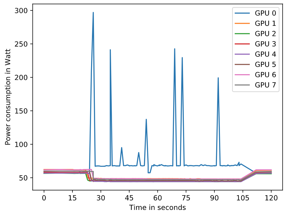
Controlling power draw during the AI application run with GPU, the author selected only a single GPU device for inference. Figure 3.3 shows a test run on GPU with ID 0. Persistence mode is enabled and the power cap is set to its maximum at 300 Watt. GPU devices 1 to 7 run idle. The run takes ca. 80 seconds. While other GPU run idle at very low power consumption under 50 Watt each, the GPU device the inference job is assigned to, hits its peak power draw of 300 Watt and ca. 250 Watt multiple times during the computation of convolutions. Combining GPU peak power consumption and one of the Intel Xeon E5-2698V4 CPU’s peak power consumption, the overall cluster power draw stayed below 2.2 kW at the third day of competition. Feeding the GPU, data is read on a single CPU, though the GPU node carries two Broadwell processors.
The data in Figure 3.3 was captured with
nvidia-smi -q -d POWER and one second between reading points. It is
likely the GPU hit 300 Watt multiple times within milliseconds.
Exceeding the GPU’s TDP of 300 Watt was prevented by setting a hard
power cap of 300 Watt through the nvidia-smi interface.
Conclusions
The competition’s main challenge is its power limitation. Recent multi-core processors are well optimised to reach highest performance under optimised power efficiency. The key to successful runs at SCC is to find optimal application configurations balancing performance and power consumption. The hyperparameter optimisation inevitably included a multitude of evaluation runs. Our evaluation was based on correctness, performance metrics (e.g. Flops) and particularly the cluster’s overall power draw.
Test systems and the cluster’s architecture changed before the competition days. Scripting as many build-steps as possible we automated and guaranteed fast transition from a test to a production system. Writing build and staging scripts works as automation and documentation. The second day we added a kill script ending processes when the cluster’s power draw approaches 3kW proves preventing us from penalties for crossing the power budget.
Having decided on the cluster’s architecture and its components, our setup still held potential for further power reduction measures. Using a multi-node system, latency sensitive applications were accelerated through Infiniband. Only the system’s headnode required internet connection, making it possible for us to remove unnecessary ethernet network cards on individual nodes further reducing the cluster’s overall power consumption. We successfully deployed our system in the Student Cluster Competition and made use of high-performing accelerators and Infiniband networking.